Los Alamos R&D

Los Alamos National Laboratory · Accelerators and Electrodynamics (AOT-AE)

LosAlamos

Four years and ten months on the mesa

I was an R&D engineer in an accelerator group at Los Alamos. I designed the magnetic lens for our diamond cathodes, and it’s patented.110 I also built the field mapper for the Scorpius solenoids, and plenty of other test gear and the code that ran it.R

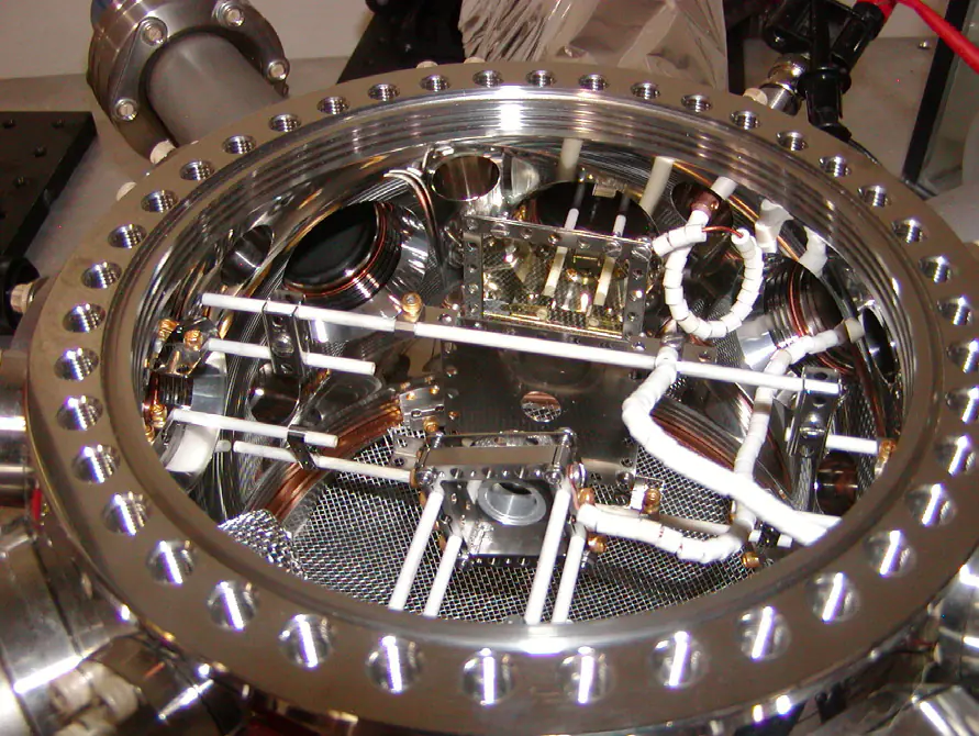
Looking down into a round stainless vacuum chamber through its open top flange: ceramic rods, beaded wires, a perforated floor and the cathode mount.
The small experiment chamber, from the top. The cathode holder, mesh anode and phosphor sit in a line, close to far. Figure 3 of H. L. Andrews, B. K. Choi, R. L. Fleming et al., Current Experimental Work with Diamond Field-Emitter Array Cathodes, FEL’17, JACoW Publishing, doi:10.18429/JACoW-FEL2017-WEP015, CC BY 3.0.
01

On the mesa

Jan 2017 – Oct 2021

  1. I started as a post-bac in AOT-AE, the Accelerators and Electrodynamics group. Python control software, live video in the data collection, and SolidWorks designs for the diamond cathode tests.OR

  2. My name’s on a paper for the first time, at FEL’17: diamond field-emitter array cathodes, run a few millimeters from the anode.67

  3. IPAC’18, my first poster, on the lens for our diamond cathodes: two ring magnets, a focus you set with a spanner wrench, and a 75 µm spot on the first test.10

  4. I presented the lens again at AAC’18, in IEEE’s proceedings next to two of our diamond cathode papers.121314

  5. Modeling the diamond emitters, in the Journal of Applied Physics.2

  6. IPAC’19: divergence and focusing from a single pyramid. The wire scan read 5.72 µm.15

  7. The lens patent application went in.1

  8. NAPAC’19. I presented what an 80 µm wire can and can’t tell you about a 10 µm spot.18

  9. Divergence and emittance from a single diamond pyramid, in Nuclear Instruments and Methods A.3

  10. C-band. The 50 MW klystron came in 2019, 25 tons of lead in 2020, and the first cavity went under power in May 2021.21

  11. The patent was granted, US 10,998,158.1

  12. I left for a Python job at FireMon.R

  13. Two Applied Physics Letters papers came out after I left: photocathode films grown under feedback, and the C-band cavities.45

Also on my resumeR

  • Got picked to present our results and methods at international conferences.
  • My first conference poster was at IPAC, on the DFEA cathodes. I also presented at AAC and at DESY in Hamburg.
  • Went to USPAS, the US Particle Accelerator School, for accelerator and advanced physics courses in Chicago.
  • Wrote high-speed data acquisition in Python, plus Jupyter tooling that automated the processing and the reports.
  • Wrote C++, C# and Python to control experiments and record their data.
02

The lens

Variable-focus magnetostatic lens · US 10,998,158

A diamond tip throws its electrons out in a cone 5 to 10 degrees wide.10 A laser accelerator needs them squeezed into a micron or two.18

The lens is two permanent ring magnets in iron yokes, set in a Thorlabs lens tube with like poles facing. They push apart, so they stay lined up.10 Closer together, their fields cancel and the lens gets weaker. Farther apart, it gets stronger. The second magnet also undoes the twist the first one puts in the beam.1 You set the gap with a spanner wrench on a retaining ring.10

Copper irises cut off the outer electrons, which focus short. You lose current and get a smaller spot.10 The patent puts it at about 90% of an ideal lens for 5% of the cost.1 I still like that it’s two off-the-shelf magnets in a lens tube, and you focus it with a wrench.

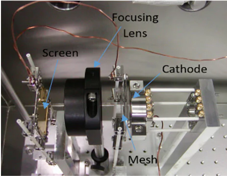
The lens on an optics bench in the chamber: a black lens tube between the cathode mount and the screen, labeled Focusing Lens, Screen, Cathode and Mesh.
The lens on the bench, between the cathode and the screen. Figure 6(a) of R. L. Fleming et al., A Simple Variable Focus Lens for Field Emitter Cathodes, IPAC’18, JACoW Publishing, doi:10.18429/JACoW-IPAC2018-THPAL024, CC BY 3.0.

Drag the gap and watch the focus move. Close the iris for a smaller spot.

Pick a plane, then drag the wire across the beam and watch its shadow.

Side view · tip to screen

On-axis field and twist

Controls

Plane
Wire

Screen

Readout

In the papers. IPAC’18: magnets 6.5 mm apart, 950 G peak, a focal length expected between 19.6 and 28.9 mm. We moved the screen from 41.4 mm in to 15.5 mm and found the focus at 23.5 mm: a 75 µm spot carrying 8.3 µA.10 NAPAC’19: 1200 G, and GPT put a 10 µm focus 15.1 mm from the center.18

This model. Two opposed Glaser bell fields, fitted to one number from the paper (950 G at 6.5 mm), with 40 kV electrons from a tip 53.6 mm upstream. The real lens was worked out in POISSON and GPT with its iron yokes, so these numbers are only the right size.

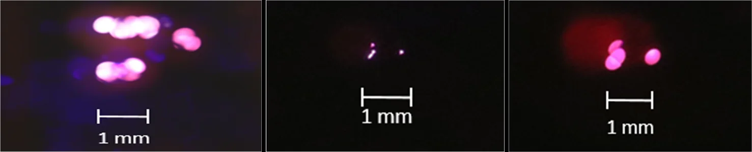
Three glowing spots on the phosphor screen with 1 mm scale bars: many beamlets with no lens, one tight spot at the focus, and a larger spot past it.
No lens, then focused at 23.5 mm (75 µm), then past the focus at 30.5 mm (197 µm). There are fewer beamlets with the lens in because of the collimator. Figure 7 of R. L. Fleming et al., A Simple Variable Focus Lens for Field Emitter Cathodes, IPAC’18, JACoW Publishing, doi:10.18429/JACoW-IPAC2018-THPAL024, CC BY 3.0.

It got the beam to 75 µm on its first test. A laser accelerator wants a micron or two, so it was a first step.1018

03

The wire

Focusing studies · NAPAC’19

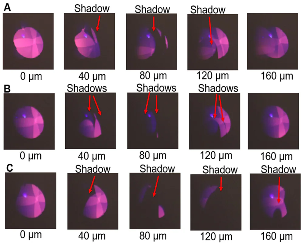
To measure a spot this small we pulled a copper wire across the beam in 1 µm steps and read the current it caught.1518 The shadow on the screen behind it tells you where you are. Before the focus it runs the other way. After the focus it follows the wire. At the focus it closes in from both sides.18

That last one was the catch. An 80 µm wire scanned across a 10 µm spot reads about 90 µm, and most of that is wire. So we tried a 5 µm tungsten wire, and the 40 keV electrons went through its thin edges. They get about 2.71 µm into tungsten.18 The next plan was a knife edge.

Try it in the instrument above: , pick plane A, B or C, and drag the wire.

Three rows of five beam images with a red arrow on each marking the wire's shadow as the wire moves 40 µm at a time, at planes A, B and C.
The wire’s shadow at planes A, B and C, 40 µm per frame. Figure 2 of R. L. Fleming et al., Focusing Studies of an Electron Beam in Diamond Field Emitter Array Cathodes, NAPAC’19, JACoW Publishing, doi:10.18429/JACoW-NAPAC2019-MOPLH22, CC BY 3.0.
04

Scorpius

Self-correcting 3D field mapper · pulsed wire

Scorpius is the accelerator NNSA’s labs are building to X-ray subcritical plutonium experiments, nearly 1,000 feet underground in Nevada. It’s 400 feet long, with 102 cells about 3 feet across. Each module has to line up with the next within microns.SN

I built a self-correcting 3D field mapper for our solenoid test stand. The solenoids were huge, 3 by 2 feet and bigger, under a plastic shielding box. A wire ran through one from end to end, over a pulley with a known weight on it. A gauge on the other end read its tension.

My GUI started with a calibration, from the solenoid’s physical center to the wire. Then an amplifier I made sent one spike of a square wave down the wire, at an exact frequency and amplitude. The spike kicked the wire, and two XY laser micrometers, calibrated to Thorlabs stages that moved in three axes, recorded it. My Python kept it all in sync. Then a formula of Kip’s (thanks, Kip) turned the wire’s motion back into the field along it. Do that at enough positions and angles and you’ve mapped the magnet in 3D.

You told the script the resolution, how many redundant points to take and the rest of the setup, and pressed GO. It mapped and calibrated the magnet on its own. It was built to do that for thousands of solenoids for the labs. I wrote all the code, did all the machine drawings and the electrical work, and nearly all the math.R

  1. AnchorOne end of the wire, with a gauge on its tension.
  2. Micrometer AAn XY laser micrometer, calibrated to a Thorlabs stage that moves in three axes.
  3. Solenoid3 by 2 feet and bigger, under a plastic shielding box.
  4. Micrometer BThe second one, at the other end.
  5. Pulley and weightA known weight sets the tension.
  6. Pulse amplifierMine. One square spike at an exact frequency and amplitude.
  7. ComputerMy Python and GUI, with the calibration, the stages, the pulse and the readings in sync.

Press Pulse and watch the kick run down the wire. Then pick Mystery and press GO.

Side view · anchor to pulley

Controls

Magnet

Bore · looking down the wire

Readout

Back to the field · micrometer B

In the method papers. The pulsed-wire method came from R. W. Warren at Los Alamos, for wigglers.WP On a solenoid, a short pulse moves the wire in proportion to the field’s first integral, from the micrometer back to where the wave left. An offset gives a bump that comes back to zero. A tilt gives a step that stays.P

This model. A 0.6 m solenoid, 6 m of 100 µm copper-beryllium wire under 0.5 kg, 5 A pulses and 0.05 µm of micrometer noise a shot. The wire is an ideal string with its echoes, and leaves out its stiffness, sag and heating. Here the stages land 3% long and 2° off square, so GO checks its own moves. These aren’t the test stand’s numbers.

05

The chamber

Cathode test stand

The cathodes ran in a vacuum test stand at 40 kV, from a −60 kV supply on the cathode mount, with an ion gauge next to the cathode and an RGA for the gases.611 The anode rode a motorized in-vacuum XY stage with 25 nm resolution, and the wire and the screen had a stage of their own.1115 I designed and put together several vacuum chambers there. I also built a diamond amplifier chamber, with its SolidWorks models, machine drawings, wiring and the software that ran it.R

The purple beam photos in this room are in focus because of a stage I designed in SolidWorks. Its mount was isolated to hold off 40 kV in vacuum at micron gaps, with no arcing. My C++ GUI stepped the stage and sent the camera lens a voltage that moved it forward or back by the same step. It took so much iteration.R

It’s a sketch, put together from the papers’ descriptions and the photo at the top. Drag to turn it, and scroll or pinch to zoom. The beam and the magnets follow the lens above.

  1. Cathode mountThe diamond array, at −40 kV.618
  2. Mesh anode100 lines per inch, 5.5 mm from the tip, on a motorized stage.1118
  3. The lensTwo ring magnets in iron yokes, in a lens tube.10
  4. Wire holderAn 80 µm copper wire across the holder’s opening.18
  5. AZO screenZnO:Al₂O₃ on sapphire, read through 20 kΩ to ground.15
  6. Ion gaugeNext to the cathode and the anode.6
  7. RGAA residual gas analyzer, for what’s in the vacuum.6
  8. HV feedthroughFrom the −60 kV supply.6
  9. Viewport and cameraOn the screen.15
  10. Pumping portThe papers don’t say which pumps.

Test stand · a sketch

06

C-band

CERF-NM · 5.712 GHz

The 2021 papers are from C-band, at CERF-NM, a test stand in the old LEDA tunnel.21 A 50 MW Canon klystron at 5.712 GHz feeds a waveguide line that seven pumps hold at 10⁻¹⁰ Torr. The cavity sits inside about 25 tons of lead.2123

The first two cavities came from SLAC, one copper and one copper-silver, built for protons at half the speed of light. Both went past 200 MV/m, and the copper-silver one held about 20% more field at the same breakdown rate.524

Conditioning a cavity takes weeks,21 so the loop got automated. Step the power up while breakdowns stay rare, and back off when they don’t. A breakdown is the Faraday cup going over 25 mV.23

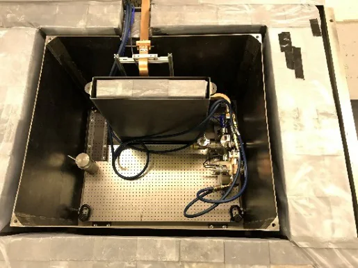
Looking down into the open lead enclosure at CERF-NM: a black-walled box with the cavity and waveguide parts on a breadboard, cables and a copper waveguide coming in from the top.
CERF-NM, inside the lead enclosure. Figure 1(b) of M. Schneider, R. Fleming et al., FEbreak: A Comprehensive Diagnostic and Automated Conditioning Interface for Analysis of Breakdown and Dark Current Effects, IPAC’21, JACoW Publishing, doi:10.18429/JACoW-IPAC2021-THPAB138, CC BY 3.0.

Conditioning · a toy

The loop is the one in the FEbreak paper.23 The breakdown odds are made up, and 4 MW is 161 MV/m, as in the paper’s first cavity.

07

The ion source

RFQ project · LANSCE

LANSCE was replacing its old H+ injector, a 750 kV Cockcroft-Walton, with an RFQ. The new injector got a test stand of its own.L My coworker Ilija designed and built an H+ plasma source for the project. He and I kept it running on our own for a long stretch.

I mostly maintained it and followed his lead, and I did everything that was code. It was a lot of Allen-Bradley work, wiring, LabVIEW and other electrical work. I also designed and built the safety interlock for its tests.R

08

Papers and talks

Every one has my name on it, R. L. Fleming at LANL, ORCID 0000-0002-0897-3742. The JACoW and OSTI copies are free to read.

Patent

  1. Variable-focus magnetostatic lens

    J. Lewellen, K. Nichols, H. Andrews, R. Fleming

    US 10,998,158 B1 · filed Jun 2019, granted May 2021 · Inventor · PDF · OSTI

Journals

  1. Modeling of diamond field emitter arrays for a compact source of high brightness electron beams

    C.-K. Huang, H. L. Andrews, R. C. Baker, R. L. Fleming, D. Kim, T. J. T. Kwan, A. Piryatinski, V. Pavlenko, E. I. Simakov

    Journal of Applied Physics 125, 164501 (2019) · OSTI

  2. Divergence study and emittance measurements for the electron beam emitted from a diamond pyramid

    D. Kim, H. L. Andrews, B. K. Choi, R. L. Fleming, C.-K. Huang, T. J. T. Kwan, J. W. Lewellen, K. Nichols, V. Pavlenko, E. I. Simakov

    Nuclear Instruments and Methods A 953, 163055 (2020) · OSTI

  3. Stoichiometry control and automated growth of alkali antimonide photocathode films by molecular beam deposition

    V. Pavlenko, J. Smedley, A. Scheinker, R. L. Fleming, A. Alexander, M. A. Hoffbauer, N. A. Moody

    Applied Physics Letters 120, 091901 (2022) · OSTI

  4. High gradient off-axis coupled C-band Cu and CuAg accelerating structures

    M. Schneider, V. Dolgashev, J. W. Lewellen, S. G. Tantawi, E. A. Nanni, M. Zuboraj, R. Fleming, D. Gorelov, M. Middendorf, E. I. Simakov

    Applied Physics Letters 121, 254101 (2022) · arXiv

Conferences

  1. Current Experimental Work with Diamond Field-Emitter Array Cathodes

    H. L. Andrews, B. K. Choi, R. L. Fleming, J. W. Lewellen, K. Nichols, D. Yu. Shchegolkov, E. I. Simakov

    FEL’17, Santa Fe, WEP015 · PDF

  2. Modeling of Diamond Field-Emitter Arrays for High-Brightness Photocathode Applications

    C. Huang, H. Andrews, B. Choi, R. Fleming, T. Kwan, J. Lewellen, D. Nguyen, K. Nichols, V. Pavlenko, A. Piryatinski, D. Shchegolkov, E. Simakov

    FEL’17, Santa Fe, WEP016 · PDF

  3. The Path to Compact, Efficient Solid-State Transistor-Driven Accelerators

    D. Nguyen, C. Buechler, G. Dale, V. Dolgashev, R. Fleming, M. Holloway, E. Jongewaard, J. Lewellen, E. Nanni, J. Neilson, D. Patrick, A. Sy, S. Tantawi

    IPAC’18, Vancouver, MOPML052 · PDF

  4. An Electrostatic Fixed-Slit Emittance Measurement System

    J. W. Lewellen, H. L. Andrews, R. L. Fleming, K. Nichols, E. I. Simakov

    IPAC’18, Vancouver, WEPAL045 · PDF

  5. A Simple Variable Focus Lens for Field Emitter Cathodes

    R. L. Fleming, H. L. Andrews, K. Bishofberger, D. Kim, J. W. Lewellen, K. E. Nichols, D. Y. Shchegolkov, E. I. Simakov

    IPAC’18, Vancouver, THPAL024 · First author · Presented · PDF

  6. An Investigation of Electron Beam Divergence from a Single DFEA Emitter Tip

    H. L. Andrews, B. K. Choi, R. L. Fleming, D. Kim, J. W. Lewellen, K. Nichols, D. Yu. Shchegolkov, E. I. Simakov

    IPAC’18, Vancouver, THPML007 · PDF

  7. A Simple Variable Focus Lens for Field-Emitter Cathodes

    R. L. Fleming, H. L. Andrews, K. A. Bishofberger, D. Kim, J. L. Lewellen, K. Nichols, D. Yu. Shchegolkov, E. I. Simakov

    IEEE AAC’18, Breckenridge · First author · Presented · OSTI

  8. Study of the Beam Divergence in Diamond Field Emitter Array Cathodes

    D. Kim, H. L. Andrews, R. L. Fleming, J. L. Lewellen, K. Nichols, V. Pavlenko, D. Yu. Shchegolkov, E. I. Simakov

    IEEE AAC’18, Breckenridge

  9. Field Assisted Photoemission from Nanocrystalline Diamond and Diamond Field Emitter Arrays

    V. Pavlenko, H. L. Andrews, R. J. Aragonez, R. L. Fleming, C. Huang, D. Kim, T. J. T. Kwan, A. Piryatinski, E. I. Simakov

    IEEE AAC’18, Breckenridge · OSTI · slides

  10. Analysis of Electron Beam Divergence in Diamond Field Emitter Array Cathodes

    D. Kim, R. L. Fleming, H. L. Andrews, C.-K. Huang, J. W. Lewellen, K. Nichols, V. Pavlenko, E. I. Simakov, B. K. Choi

    IPAC’19, Melbourne, TUPTS073 · PDF

  11. Observations of the Femtosecond Laser-Induced Emission From the Diamond Field Emitter Tips

    E. I. Simakov, H. Andrews, D. Black, R. Fleming, D. Kim, K. Leedle, V. Pavlenko

    IPAC’19, Melbourne, TUPTS089 · PDF

  12. Physics of Electron Beam Generation and Dynamics From Diamond Field Emitter Arrays

    C. Huang, H. Andrews, R. Baker, R. Fleming, D. Kim, T. Kwan, V. Pavlenko, A. Piryatinski, E. Simakov

    IPAC’19, Melbourne, TUPTS091 · PDF

  13. Focusing Studies of an Electron Beam in Diamond Field Emitter Array Cathodes

    R. L. Fleming, H. L. Andrews, D. Gorelov, C. Huang, D. Kim, J. W. Lewellen, K. E. Nichols, V. N. Pavlenko, E. I. Simakov

    NAPAC’19, Lansing, MOPLH22 · First author · Presented · PDF

  14. Characterization of Femtosecond-Laser-Induced Electron Emission from Diamond Nano-Tips

    V. Pavlenko, H. Andrews, D. Black, R. Fleming, D. Gorelov, D. Kim, K. Leedle, E. Simakov

    NAPAC’19, Lansing, MOPLH25 · PDF

  15. Physics of Electron Emission and Beam Dynamics from a Single Diamond Field Emitter

    C. Huang, T. J. T. Kwan, A. Piryatinski, R. C. Baker, D. Kim, V. Pavlenko, H. L. Andrews, R. L. Fleming, E. I. Simakov

    IEEE ICOPS 2020, abstract

  16. Status of the C-Band Engineering Research Facility (CERF-NM) Test Stand Development at LANL

    D. Gorelov, R. Fleming, S. Lawrence, J. Lewellen, M. Middendorf, D. Perez, M. Schneider, E. Simakov, T. Tajima

    IPAC’21, online, MOPAB146 · PDF

  17. First C-Band High Gradient Cavity Testing Results at LANL

    E. Simakov, R. Fleming, D. Gorelov, T. Jankowski, M. Kirshner, J. Lewellen, X. Lu, M. Middendorf, E. Nanni, J. Pizzolatto, M. Schneider, T. Tajima, S. Tantawi

    IPAC’21, online, MOPAB341 · PDF

  18. FEbreak: A Comprehensive Diagnostic and Automated Conditioning Interface for Analysis of Breakdown and Dark Current Effects

    M. Schneider, S. Baryshev, R. Fleming, D. Gorelov, E. Jevarjian, J. Lewellen, E. Simakov

    IPAC’21, online, THPAB138 · PDF

  19. High Gradient Conditioning and Performance of C-Band β=0.5 Proton Normal-Conducting Copper and Copper-Silver Radio-Frequency Accelerating Cavities

    M. Zuboraj, S. Baryshev, V. Dolgashev, R. Fleming, D. Gorelov, E. Jevarjian, J. Lewellen, M. Middendorf, E. Nanni, M. Schneider, E. Simakov, E. Snively, S. Tantawi

    IPAC’22, Bangkok, TUPOMS060 · PDF · OSTI
Other sources

09

Watch and read

On lanl.gov